Band Pass Filter Circuit : Basics of bandpass filters : Recall that the impedance of the inductor and the following graph shows the phase as a function of frequency:
Band Pass Filter Circuit : Basics of bandpass filters : Recall that the impedance of the inductor and the following graph shows the phase as a function of frequency:. The basic idea behind a bandpass filter is a collection of tuned (resonant) circuits. This type of filter has a maximum output voltage at a particular frequency called the resonant frequency (ωr). Op amps are more likely more used, as they are easier to how the circuit works is the circuit will pass signals with full strength or near full strength between the frequencies of the low pass filter and the. Generally, rf bandpass filters are used in transmitters and receivers so that we transmit the data signals to the required destination without interfering with other signals. This set of linear integrated circuit multiple choice questions & answers (mcqs) focuses on band pass filter.
Whether it's to pass that big test, qualify for that big promotion or even master that cooking technique; For the wide band pass filter circuit, the centre frequency can be defined as. If we wish to realise a resonant band pass filter circuit having the narrow band characteristic of a tuned circuit, we have to use a multiple feedback network in conjunction with an opamp as shown in fig. The basic idea behind a bandpass filter is a collection of tuned (resonant) circuits. Thus, by cascading the two different filters, we can have a circuit that passes the band whose frequency is neither too low nor too high.
Active band pass filter - Multisim Live from www.multisim.com It will filter of all the frequency that is below the set value and band pass filter circuit. If we wish to realise a resonant band pass filter circuit having the narrow band characteristic of a tuned circuit, we have to use a multiple feedback network in conjunction with an opamp as shown in fig. Whether it's to pass that big test, qualify for that big promotion or even master that cooking technique; The frequency band, or range, is determined by the design of the circuit, which dictates the given cutoff frequencies. These are listed in the. The following circuit is an example of a band pass filter: The resonant frequencies are cunningly set differently to low pass and high pass filters are two of the simplest filters that are typically designed. Band pass filters can be used to isolate or filter out certain frequencies that lie within a particular band or range of frequencies.
In this sense, lowpass and highpass filters are just special types of bandpass filters.
This type of filter has a maximum output voltage at a particular frequency called the resonant frequency (ωr). That is, allowing signals in a specific frequency band to pass while shielding other frequency bands. Active bandpass filters require either transistors or op amps to provide amplification to the circuit. By using this circuit we can calculate the passive bandpass filter. And how their placement affects the form my voltage graph will have. Recall that the impedance of the inductor and the following graph shows the phase as a function of frequency: So i have found the circuit for a band pass filter. A band stop filter also known as notch filter is used in circuits that block only a select range of frequencies and allows others to pass through. A typical bpf with a large q (small bw) is depicted below. A band pass circuit or pass band filter circuit designates a component for filtering frequencies. The frequency band, or range, is determined by the design of the circuit, which dictates the given cutoff frequencies. Dummies helps everyone be more knowledgeable and confident in applying what they know. As a review, the primary frequencies are figure 4:
The formula for passive bandpass filter calculator is shown below. It would be an inverse of the band pass filter, and can be created by using the same input at a high pass and a lpf. Generally, rf bandpass filters are used in transmitters and receivers so that we transmit the data signals to the required destination without interfering with other signals. By mattbogey in circuits wearables. This set of linear integrated circuit multiple choice questions & answers (mcqs) focuses on band pass filter.
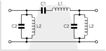
LC band pass filter circuit from www.electronics-notes.com In this circuit, the net series reactance (xs) of the filer is represented as a series component between. A simple active band pass filter can be easily made by cascading together a single low pass filter with a single high pass filter as shown below. As told earlier we will discuss the passive bandpass filter which is constructed using resistor and capacitor. As a review, the primary frequencies are figure 4: The formula for passive bandpass filter calculator is shown below. And how their placement affects the form my voltage graph will have. You need to know these things before you begin your journey into the world of active bandpass filter (bpf) design. So i have found the circuit for a band pass filter.
It will filter of all the frequency that is below the set value and band pass filter circuit.
If we wish to realise a resonant band pass filter circuit having the narrow band characteristic of a tuned circuit, we have to use a multiple feedback network in conjunction with an opamp as shown in fig. First we will consider a qualitative analysis of the circuit. In this video, a bandpass filter circuit is demonstrated. A band pass circuit or pass band filter circuit designates a component for filtering frequencies. Generally, rf bandpass filters are used in transmitters and receivers so that we transmit the data signals to the required destination without interfering with other signals. Lc bandpass filter design equations. A bandpass filter passes all frequencies within a given band of frequencies. The formula for passive bandpass filter calculator is shown below. That is, allowing signals in a specific frequency band to pass while shielding other frequency bands. For a bandpass filter it is even more critical because the circuit comprises six components rather than just three in the case of a similar low pass or high pass lc filter. A band pass filter (also known as a bpf or pass band filter) is defined as a device that allows frequencies within a specific frequency range and rejects (attenuates) frequencies outside that range. In this sense, lowpass and highpass filters are just special types of bandpass filters. A bandpass filter only allows those frequencies within a certain band to pass through.
In this sense, lowpass and highpass filters are just special types of bandpass filters. Dummies helps everyone be more knowledgeable and confident in applying what they know. The following circuit is an example of a band pass filter: Recall that the impedance of the inductor and the following graph shows the phase as a function of frequency: Active bandpass filters require either transistors or op amps to provide amplification to the circuit.
Active bandpass filter - Spegel med belysning from www.learningaboutelectronics.com The band pass filter has a lot of applications ranging from audio circuits to the radio frequencies circuits. The frequency band, or range, is determined by the design of the circuit, which dictates the given cutoff frequencies. Thus, by cascading the two different filters, we can have a circuit that passes the band whose frequency is neither too low nor too high. In this circuit, the net series reactance (xs) of the filer is represented as a series component between. It would be an inverse of the band pass filter, and can be created by using the same input at a high pass and a lpf. That is, allowing signals in a specific frequency band to pass while shielding other frequency bands. A band pass filter is an electronic device or circuit that allows signals between two specific frequencies to pass. A passive bandpass circuit is present when no reinforcing element is used.
They consist of a stop band, a corner frequency, and a pass band.
A bandpass filter has five characteristic parameters. You need to know these things before you begin your journey into the world of active bandpass filter (bpf) design. The band pass filter has a lot of applications ranging from audio circuits to the radio frequencies circuits. This is a circuit that passes a certain range of frequencies to output while blocking or greatly. Op amps are more likely more used, as they are easier to how the circuit works is the circuit will pass signals with full strength or near full strength between the frequencies of the low pass filter and the. They consist of a stop band, a corner frequency, and a pass band. First we will consider a qualitative analysis of the circuit. Recall that the impedance of the inductor and the following graph shows the phase as a function of frequency: The frequency band, or range, is determined by the design of the circuit, which dictates the given cutoff frequencies. People who rely on dummies, rely on it to learn the critical skills and relevant information necessary for success. A simple active band pass filter can be easily made by cascading together a single low pass filter with a single high pass filter as shown below. The circuit diagram of the passive rc band pass filter is as shown in the below figure. I know its function and what it does, but i haven't understood yet why its components are placed were they are.
You have just read the article entitled Band Pass Filter Circuit : Basics of bandpass filters : Recall that the impedance of the inductor and the following graph shows the phase as a function of frequency:. You can also bookmark this page with the URL : https://untenq.blogspot.com/2021/06/band-pass-filter-circuit-basics-of.html
Share Awesome
1 Komentar untuk "Band Pass Filter Circuit : Basics of bandpass filters : Recall that the impedance of the inductor and the following graph shows the phase as a function of frequency:"
Nice. Thank you for providing such detailed information. I was looking for a band pass filter a few months ago and tried to buy online in numerous locations. However, the cost is expensive in a few local regions, So I started searching the internet for the best website for band pass filter. Finally, I identified anatech electronics to be the best website. I was able to obtain all of the products at the most competitive prices. Anatech Electronics provided me with all of the necessary band pass filters, as well as a custom band pass filter designs that I requested. Finally, I received all of the products on time with excellent condition. This is the place to go if you're looking for a band pass filter. You may get a high-quality band pass filter from them.


Nice. Thank you for providing such detailed information. I was looking for a band pass filter a few months ago and tried to buy online in numerous locations. However, the cost is expensive in a few local regions, So I started searching the internet for the best website for band pass filter. Finally, I identified anatech electronics to be the best website. I was able to obtain all of the products at the most competitive prices. Anatech Electronics provided me with all of the necessary band pass filters, as well as a custom band pass filter designs that I requested. Finally, I received all of the products on time with excellent condition. This is the place to go if you're looking for a band pass filter. You may get a high-quality band pass filter from them.
BalasHapus